-
E-mail
13384303373@163.com
-
Phone
13384303373
-
Address
No. 468 Yinjin Road, Jingyue High tech Development Zone, Changchun City, Jilin Province
Product Categories
- High-temperature extensometer
- Thermal expansion measuring instrument
- High and low temperature environmental chamber
- High temperature vacuum furnace
- Endurance creep testing machine
- force sensor
- Low temperature environment device
- Microscopic in-situ nanomechanical testing equipment
- Oil source pipeline system
- High temperature atmospheric furnace
- actuator
- Multi channel data acquisition controller
- Specialized component fatigue test bench
- impact testing machine
- vibration table
Changchun Deli Measurement and Control Test System Co., Ltd
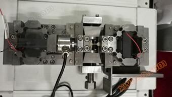
DKTP Micro Mechanical Tensile Low Cycle Fatigue Tester
NegotiableUpdate on 03/26
- Model
- Nature of the Manufacturer
- Producers
- Product Category
- Place of Origin
Overview
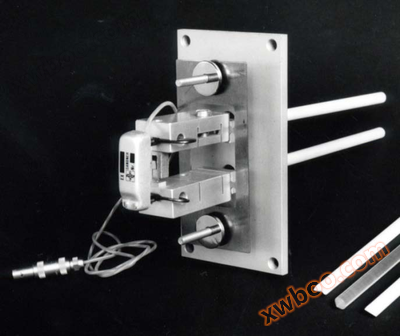
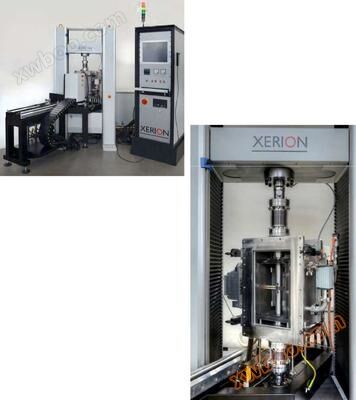
DKTP micro mechanical tensile low cycle fatigue tester is one of the most typical static and dynamic in-situ testing technologies that can visually monitor material micro deformation damage and structural changes. Our company has developed and produced commercial in-situ tensile low cycle fatigue testers for material micro mechanical performance testing and characterization, including ultra precision in-situ tensile low cycle fatigue tester (Figure 1) and large range in-situ tensile low cycle fatigue tester (Figure 4)
Product Details
DKTP Micro Mechanical Tensile Low Cycle Fatigue Tester
DKTP micro mechanical tensile low cycle fatigue tester is one of the most typical static and dynamic in-situ testing technologies that can visually monitor the micro deformation damage and structural changes of materials. Our company has developed and produced commercial in-situ tensile low cycle fatigue testers for the micro mechanical performance testing and characterization of materials, including ultra precision in-situ tensile low cycle fatigue tester (Figure 1) and large range in-situ tensile low cycle fatigue tester (Figure 4).This series of experimental equipment was jointly developed with a research team from Jilin University.
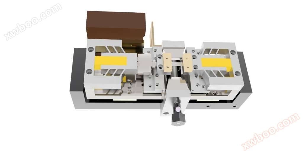
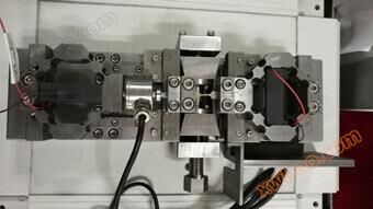
Figure 1 Ultra precision in-situ tensile low cycle fatigue tester
application
metal material
alloy material
ceramic materials
bionic materials
composite material
Features and advantages
Ultra precision in-situ tensile low cycle fatigue tester provides precise technical support for material preparation, life sciences, aerospace, and interstellar exploration
A compact ultra precision in-situ tensile low cycle fatigue tester has been developed, which is compatible with optical microscopy imaging equipment
Realize dynamic in-situ observation of material micro deformation damage mechanism and microstructure evolution under load
In depth study of the macroscopic mechanical behavior and microstructural evolution of materials
Equipped with a control host, dedicated detection and control system, and supporting analysis and processing software
advanced design
Piezoelectric actuation ultra precision in-situ tensile low cycle fatigue tester, achieving small size, compact structure, and compatibility with various observation devices
Addressing the issues of long testing cycles and high energy consumption caused by traditional fatigue testing devices primarily relying on testing life curves
Solved the problem that traditional fatigue devices cannot achieve real-time observation of material specimens
Obtaining higher quality images during in-situ observation can provide clearer and more accurate observation and analysis of microstructure
The curves of the elastic stage and pre fracture load of the material over time were measured by instruments, as shown in Figure 2. The in-situ observation image of the surface morphology of the tested material is shown in Figure 3.
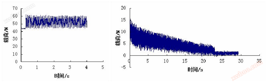
Figure 2 Time varying curves of elastic stage and pre fracture load of material (aluminum alloy)
As shown in Figure 2, the curve of the 30 second load variation between the elastic stage and the final fracture shows that 6061 aluminum alloy still exhibits significant plasticity under the action of tensile fatigue coupling load.
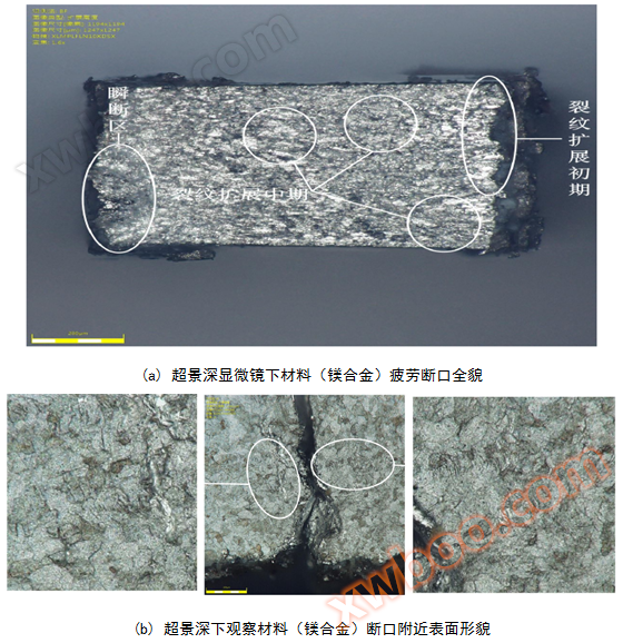
Figure 3 In situ observation image of surface morphology of test material
As shown in Figure 3 (a), the entire fracture surface can be roughly divided into three regions: the early stage of crack propagation, the middle stage of crack propagation, and the instantaneous fracture zone. As shown in Figure 3 (b), it was found that the fracture of magnesium alloy under tensile fatigue load is a mixture of intergranular fracture and transgranular fracture. There are a large number of shell like folds near the main crack, indicating that surface dislocations occurred due to compression during crack initiation and propagation.
Technical specifications of ultra precision in-situ tensile low cycle fatigue tester (series PL01, PL02, PLP01, etc.)
Maximum load capacity: 1000N, 3000N (series)
Loading force resolution: 100mN
Fatigue test frequency: 0.001-1Hz/10-20Hz
Range of force testing: 1% to 100% FS
Force measurement accuracy: ± 1% indication
Displacement resolution: 1 μ m
Loading stroke: 10mm
Test speed range: 0-6.5/min
Displacement velocity accuracy: better than ± 0.5% (unloaded)
Speed load capacity: Maximum allowable test force below 3mm/min
Input waveform of piezoelectric stack: sine wave
Sample size: millimeter level
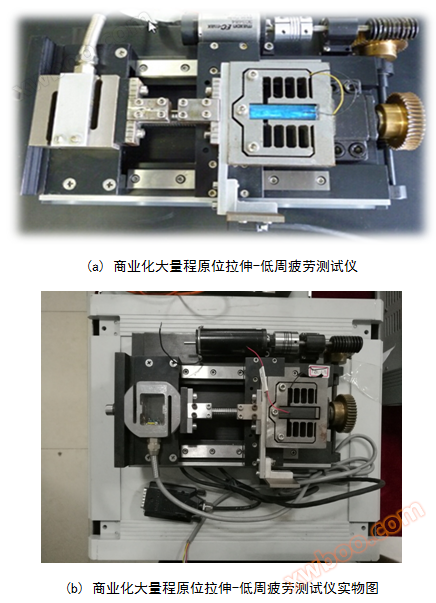
Figure 4 Large range in-situ tensile low cycle fatigue tester
application
metal material
alloy material
ceramic materials
bionic materials
composite material
Features and advantages
A large in-situ tensile low cycle fatigue tester provides precise technical support for material preparation, life sciences, aerospace, and interstellar exploration.
A compact in-situ tensile low cycle fatigue tester with a large range has been developed, which is compatible with optical microscopy imaging equipment
Realize dynamic in-situ observation of material micro deformation damage mechanism and microstructure evolution under load
In depth study of the macroscopic mechanical behavior and microstructural evolution of materials
Equipped with a control host, dedicated detection and control system, and supporting analysis and processing software
advanced design
Using a precision drive unit as the power source and displacement signal output, the precision transmission unit decelerates and amplifies the torque and converts the motion mode, converting the rotational motion into linear motion to apply tensile load to the specimen clamped by the specimen clamping unit. The signal detection unit detects the stress and deformation of the specimen.
Realize small size, compact structure, and compatibility with various observation devices.
Solved the problem that traditional fatigue devices cannot achieve real-time observation of material specimens.
Obtaining higher quality images during in-situ observation can provide clearer and more accurate observation and analysis of microstructure
The material test curve measured by the instrument is shown in Figure 5, and the in-situ observation image of the surface morphology of the tested material is shown in Figure 6.
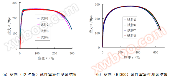
Figure 5 Material Test Curve
As shown in Figure 5, the experimental data during the elastic stage showed a repeatability error of 3.2%, indicating excellent repeatability.
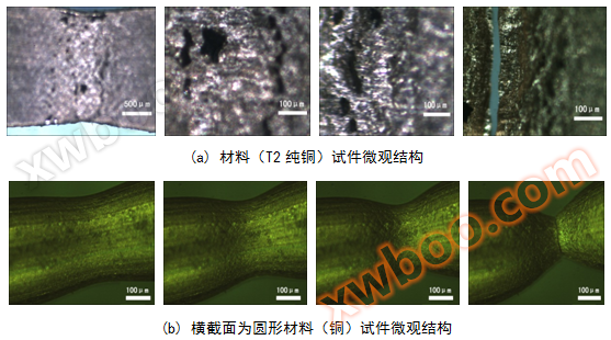
Figure 6 In situ observation image of material surface morphology
As shown in Figure 6, a fish scale texture appears on the surface of the specimen, indicating that the internal grain structure of the material has undergone significant changes until the fracture image information of the specimen appears.
Technical specifications of a large in-situ tensile low cycle fatigue tester
Maximum load capacity: 3000N
Loading force resolution: 1N
Fatigue loading frequency range: 1-50Hz
Range of force testing: 1% to 100% FS
Force measurement accuracy: ± 1% indication
Displacement resolution: 2.5 μ m
Loading stroke: 20mm
Test speed range: 0-6.5/min
Displacement velocity accuracy: better than ± 0.5% (unloaded)
Speed load capacity: Maximum allowable test force below 3mm/min
Fatigue load waveform: sine wave, triangular wave, rectangular wave, optional
Sample size: millimeter level
Similar Product Recommend